Coding a line follower using the PID controller, and calibrating the PID constants.
Line Follower
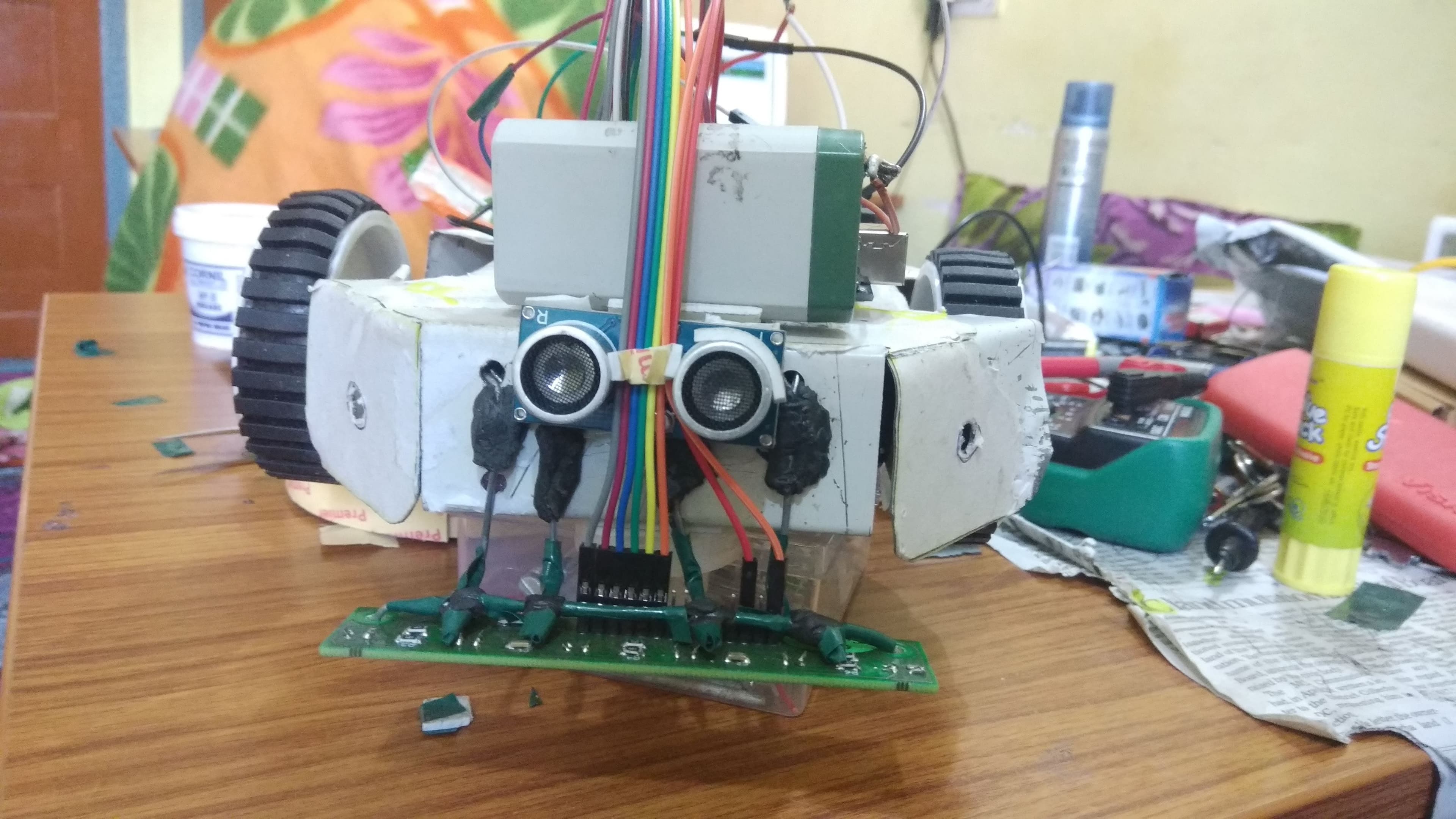
An MSR (maze solving robot) is a clever little gadget with a silicon brain that finds its way through an arbitrary maze. It competes against other members of its species, racing as fast as it can. Here MSR is an electro-mechanical device, typically consisting of three main subsystems. They are drive system, an array of sensors, and the control system.
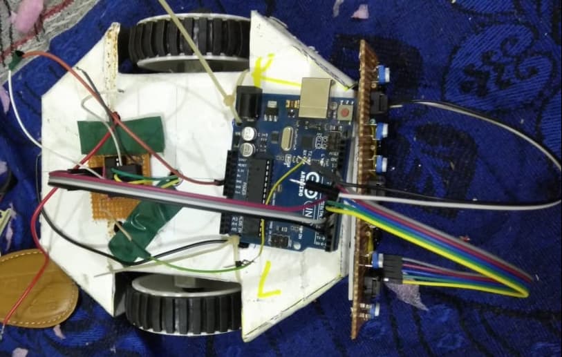
The drive system consists of a mechanical chassis, a set of motors, gears and wheels. The chassis is usually designed to operate like a wheel-chair, with two large drive wheels on either side of a lightweight aluminium frame. The chassis is built to house the motors, gear system, batteries, and circuitry, and must also be small enough to manoeuvre within the constraints of the maze.
The control system is a series of circuit boards functioning as the brain of the critter. The control system runs a maze solving algorithm (LSRB) based on the information received by the CPU (ARDUINO BOARD) from the sensors.
The final sub-system is the sensors. They report to the CPU the current state of the surroundings where the walls and paths are. These are usually either infrared sensor which picks up light reflected light of the track. The main objective is to achieve the fastest maze running time and easily find the goal.


Line Follower Bot Maze Competetion
What is PID?
PID control is the most common form of feedback control. It was an essential element of early governors and it became the standard tool when process control emerged in the 1940s. In process control today, more than 95% of the control loops are of PID type, most loops are actually PI control. PID controllers can these days be found in all areas where control is used.
Nowadays a lot of different methods for PID controller design for continuous systems exist.
These methods are compared in terms of quality of control. There are four major characteristics of the closed-loop step response: rise time, overshoot, settling time and steady-state error.
PID is a simple, yet very effective control method, in which a particular physical/electrical quantity is controlled, and made equal to a set value called the ‘set-point’. In this case, we will be controlling the speed of the right and left motors of the robot, so that the robot follows the centre of a black line using Arduino. This is done by calculating the amount of deviation of the robot from the centre of the line using IR Sensors.
PID controllers use 3 basic behaviour types of modes:
**P **— proportional
**I **— integral
**D **— derivative.
While Proportional and integrative modes are also used as single control modes a derivative mode is rarely used on its own in control systems. Such combinations such as PI and PID controller are very often in practical systems.
PID Video Tutorials
There is a great lecture on YouTube where all the different terms related to PID is cleared.
Initial Conditions
-
An array of Six IR’s Sensor is used and all are connected to analog inputs.
-
**2 DC Motors **are used and are connected to digital inputs.
-
I have used Motor Driver as an L293D IC.
-
Two PWM pins one for each motor connected to analog inputs.
-
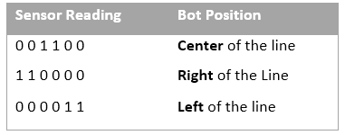
Since we are using digital IR sensors, the output of the sensors will be **0 if it detects white **and 1 if it detects black.
-
The thickness of the black line used is 3cm.
-
At a time Maximum of two sensors lie on the line.

Declarations
-
Default values for Kp, Ki, and Kd are set to 0.
-
Choose the speed of the motor from 100 to 180, if the speed of bot is very low increase. I have used 150 as the initial value.
#define l1 5
#define l2 2
#define r1 4
#define r2 3

#define enl 9
#define enr 10

int a[6];
int last_proportional = 0;
int integral = 0;
int spd = 200;
int c = 0;
float distance;

char select_turn(unsigned char found_left, unsigned char found_right, unsigned char found_st);
int mod(int v); // Modulus Function
int set_motors(int a, int b);
void turn(char dir);
void PID();

int right = 0;
int left = 0;
Read IR Sensor Values
int readline() {
  a[0] = digitalRead(A5);
  a[1] = digitalRead(A4);
  a[2] = digitalRead(A3);
  a[3] = digitalRead(A2);
  a[4] = digitalRead(A1);
  a[5] = digitalRead(A0);
  int v;
  v = (5000*a[0] + 4000*a[1] + 3000*a[2] + 2000*a[3] + 1000*a[4] + 0*a[5])/
      (a[0] + a[1] + a[2] + a[3] + a[4] + a[5]);
  return v;
}
Motor Direction and Speed
Adjust motor speed based on conditions of left and right.
Turns Left, Right, Straight, and stop on the conditions of l, and r.
void turn(char dir) { //Turning setup
  switch(dir) {
    case 'L':
      set_motors(-spd, spd);
      delay(90);
      break;
    case 'R':
      set_motors(spd, -spd);
      delay(90);
      break;
    case 'B':
      set_motors(spd, -spd);
      delay(160);
      break;
    case 'S':
      break;
  }
}

int set_motors(int l, int r) { // Motor setup
  if(l > 0 && r > 0)  {
    analogWrite(enl, mod(l));
    analogWrite(enr, mod(r));

    digitalWrite(l1, LOW);
    digitalWrite(l2, HIGH);

    digitalWrite(r1, LOW);
    digitalWrite(r2, HIGH);
  }

  else if(l < 0 && r > 0) {
    analogWrite(enl, mod(l));
    analogWrite(enr, mod(r));

    digitalWrite(l1, HIGH);
    digitalWrite(l2, LOW);

    digitalWrite(r1, LOW);
    digitalWrite(r2, HIGH);
  }

  else if(l > 0 && r < 0) {
    analogWrite(enl, mod(l));
    analogWrite(enr, mod(r));

    digitalWrite(l1, LOW);
    digitalWrite(l2, HIGH);

    digitalWrite(r1, HIGH);
    digitalWrite(r2, LOW);
  }

  else if(l == 0 && r == 0) {
    analogWrite(enl, 0);
    analogWrite(enr, 0);

    digitalWrite(l1, HIGH);
    digitalWrite(l2, HIGH);

    digitalWrite(r1, HIGH);
    digitalWrite(r2, HIGH);
  }
}
Calculating PID Values
Now, this error variable should be made use of by the calculate_pid function, which will calculate the PID value and output it to the motor. The error keeps adding itself to the Integral term during every iteration. Also, the current “error” value should become the “previous_error” value for the next iteration.
This function will run until and unless the bot is stable.
The below Kp, Ki, and Kd initial values should be found using the below article.
void PID() {
  int i;       // Control function
  int power_difference = 0;
  float Kp, Ki, Kd;
  unsigned int position;
  int derivative, proportional;
  while(1) {
    position = readline();
    Serial.println(position);
    proportional = ((int)position - 3000);

    derivative = proportional - last_proportional;
    integral = integral+proportional;

    last_proportional = proportional;
    // use the tutorial to set initial values of Kp, Ki, and Kd
    Kp = 5.5;
    Ki = 1;
    Kd = 0;

    power_difference = proportional*Kp + integral*Ki + derivative*Kd;
    const int max = spd/2 + 30;
    if(power_difference > max)
     power_difference = max;
    if(power_difference < -max)
     power_difference = (-1*max);

    if(power_difference < 0)  //left
     set_motors(max+power_difference, max);
    else  //right
     set_motors(max, max-power_difference);

    readline();

    if(a[0] == HIGH && a[1]==HIGH && a[2] == HIGH && a[3] == HIGH && a[4] == HIGH && a[5] == HIGH)
      return;
    else if(a[0] == LOW || a[5] == LOW)
      return;
  }
}
Finding Initial Values of Kp, Ki, and Kd
This is the most important part of your program. The PID constants, ie., Kp, Ki and Kd values are tuned only by trial and error method. These values will be different for every robot and for every configuration. Try this method while tuning:
-
Start with Kp, Ki and Kd equalling 0 and work with Kp first. Try setting Kp to a value of 1 and observe the robot. The goal is to get the robot to follow the line even if it is very wobbly. If the robot overshoots and loses the line, reduce the Kp value. If the robot cannot navigate a turn or seems sluggish, increase the Kp value.
-
Once the robot is able to somewhat follow the line, assign a value of 1 to Kd (skip Ki for the moment). Try increasing this value until you see a lesser amount of wobbling.
-
Once the robot is fairly stable at following the line, assign a value of 0.5 to 1.0 to Ki. If the Ki value is too high, the robot will jerk left and right quickly. If it is too low, you won’t see any perceivable difference. Since Integral is **cumulative, the Ki value has **a significant impact. You may end up adjusting it by .01 increments.
-
Once the robot is following the line with good accuracy, you can increase the speed and see if it still is able to follow the line. Speed affects the PID controller and will require retuning as the speed changes**.**
Lastly, PID doesn’t guarantee effective results just by the simple implementation of the code, it requires constant tweaking based on the circumstances, once correctly tweaked it yields exceptional results. The PID implementation also involves a settling time, hence effective results can be seen only after a certain time from the start of the run of the robot. Also to obtain a fairly accurate output it is not always necessary to implement all the three expressions of PID. If implementing just PI results yields a good result we can skip the derivative part.
Remember, your actual code should be tweaked and modified from this to work. This exact code might not work exactly how you expect unless you make changes depending on your robot’s design and connections.